
Concrete Batching Plant Common Failures and Troubleshooting Guide: Causes, Solutions & Maintenance Tips
Operating a concrete batching plant under tight production deadlines leaves no room for unexpected downtime. When a twin-shaft mixer overloads, a load cell drifts, or a pneumatic cylinder stalls, plant managers need mechanical solutions—not generic advice.

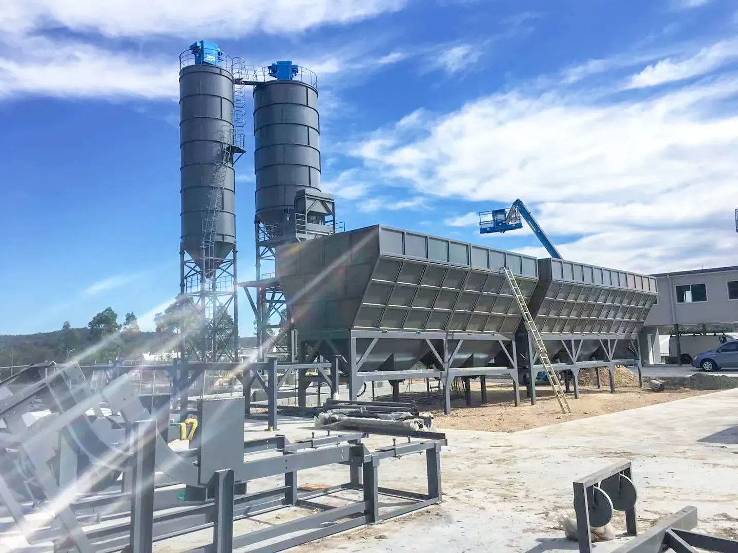
Unplanned downtime at a concrete batching plant can cost thousands of dollars per hour in wasted aggregates, ruined transit mixers, and stalled project sites. Maintaining high-volume output requires operators and maintenance technicians to diagnose mechanical, pneumatic, and electrical faults rapidly.
During field maintenance, technicians commonly find that over 70% of unexpected plant shutdowns stem from neglected daily maintenance loops—such as delayed wear-liner replacements, uncalibrated load cells, or poorly managed pneumatic water traps. Based on years of batching plant operation experience, treating symptoms rather than identifying mechanical root causes ensures the problem will return within weeks.
This guide provides a comprehensive, field-tested troubleshooting framework across the seven core subsystems of modern ready-mix and precast concrete batching plants.

1. Mixer System Failures
Mixer Motor Overheating
- Symptoms: Motor casing temperature exceeds rated limits (often tripping thermal overloads on the starter panel), distinct smell of burning insulation, or localized automated plant alarms.
- Possible Causes: Prolonged plant overloading, low voltage supply causing high amperage draw, severe concrete buildup on the mixing arms increasing mechanical resistance, or a failure of the internal cooling fan.
- Troubleshooting Steps:
- Isolate the main power supply and lock out/tag out (LOTO) the plant.
- Check the motor casing surface temperature using an infrared thermometer.
- Measure the supply voltage and operating amperage under load using a clamp meter.
- Inspect the motor's rear cooling fan cover for debris or structural damage.
- Recommended Solutions: Clean the cooling shroud immediately if blocked. If current draw exceeds nameplate full-load amps (FLA) while voltage is stable, reduce the batch volume size to nominal capacity and thoroughly clean the mixer's interior. Replace the motor bearings if manual shaft rotation reveals mechanical binding.
- Prevention Tips: Implement strict batch volume controls within design limits and clear away aggregate dust accumulations from motor cooling fins every week.
Twin Shaft Mixer Overload
- Symptoms: The PLC control panel displays an overcurrent/overload error, the main circuit breaker trips mid-cycle, or the mixing shafts visibly stall while fully loaded.
- Possible Causes: Aggregates with an oversized breakdown bypassing the grid screen, an excessively low water-to-cement ratio (dry batching), or starting the mixer while fully loaded after an abrupt emergency stop.
- Troubleshooting Steps:
- Check the material batch proportions on the PLC log to verify the exact water-to-cement ratio.
- Visually inspect the mixer interior for oversized stones trapped between the blades and liner plates.
- Test the electrical current draw during an empty start cycle.
- Recommended Solutions: Manually clear out the raw material if the mixer stalls mid-batch. Readjust the raw material feed sequence via the PLC settings to ensure water enters concurrently with aggregates, minimizing dry friction zones.
- Prevention Tips: Always verify that the hopper grizzly screens are secure to intercept oversized stone aggregates before they enter the holding hoppers.
Mixer Blade Wear
- Symptoms: Batch cycles take longer to achieve high homogeneity, concrete discharges with visible segregation, or the gap between the blade and liner exceeds 5mm.
- Possible Causes: Natural abrasive wear from processing quartz-heavy or highly angular aggregates, or operating the mixer too long without adjusting the blade clearance.
- Troubleshooting Steps:
- Shut down the plant, execute full LOTO procedures, and enter the mixing drum safely.
- Use a feeler gauge or caliper to measure the distance between the blade edge and the drum liner wall.
- Inspect the blade profile for deep gouges or missing segments.
- Recommended Solutions: Loosen the mounting bolts and adjust the adjustable blades downward to re-establish a tight 3mm to 5mm clearance gap. Replace the blades completely with high-chromium or Ni-Hard cast iron replacements if the wear surface is exhausted.
- Prevention Tips: Check and log blade clearances every 50 operating hours, making incremental adjustments before the gap grows wide enough to trap coarse aggregates.
Mixer Arm Damage
- Symptoms: Intense, rhythmic metallic banging noises inside the drum, severe structural vibration during mixing, or a sudden loss of mixing efficiency in a specific zone.
- Possible Causes: Fatigue failure from long-term cyclic loading, impact from a large foreign object (such as a dislodged steel liner plate bolt), or structural weakening caused by chronic concrete buildup.
- Troubleshooting Steps:
- Perform LOTO, clear the mixing drum completely, and check for loose or cracked arms.
- Inspect the mounting bolts securing the arm to the main hexagonal shaft.
- Recommended Solutions: Replace any cracked or structurally warped mixing arms. When installing a replacement arm, torque all high-tensile mounting bolts precisely to the manufacturer's specification and apply a thread-locking compound.
- Prevention Tips: Do not allow hardened concrete buildup to remain on the mixing arms; the added dead weight introduces severe cantilever stress during high-speed rotation.
Gearbox Abnormal Noise
- Symptoms: High-pitched whining, grinding, or deep chattering sounds emanating from the mixer drivetrain, combined with high gear-case operating temperatures.
- Possible Causes: Severely depleted gear oil levels, gear tooth chipping from shock loads, or worn internal taper-roller bearings.
- Troubleshooting Steps:
- Check the oil level sight glass on the gearbox flank.
- Extract a small oil sample to inspect for metallic flake contamination or discoloration.
- Use a mechanic's stethoscope to isolate the sound to a specific bearing housing or gear stage.
- Recommended Solutions: Drain and flush the gearbox completely if the oil shows metallic contamination, then refill with fresh heavy-duty industrial gear oil (typically ISO VG 220 or 320, depending on regional ambient temperatures). If gear teeth are chipped or pitted, rebuild or replace the gear assembly.
- Prevention Tips: Check gear oil levels weekly and execute a comprehensive oil analysis and change every 1,000 to 1,500 operating hours.
Bearing Overheating
- Symptoms: The mixing shaft main end-bearings or shaft-seal assemblies run hot to the touch (exceeding 80°C), accompanied by grease weeping or squealing.
- Possible Causes: Lack of regular lubrication, over-greasing causing internal friction, or failure of the shaft end-seal allowing highly abrasive cement grout to migrate into the roller bearings.
- Troubleshooting Steps:
- Measure the bearing housing temperature during operation using an infrared camera or thermometer.
- Inspect the purge discharge lines of the automated lubrication system to verify if grease is flowing under pressure.
- Recommended Solutions: Replace the packing seals or mechanical face seals immediately if cement grout is bypassing them. Clean out contaminated grease and pack the bearing with fresh, high-temperature extreme-pressure (EP2) lithium grease. Replace the entire bearing assembly if internal raceways show signs of spalling.
- Prevention Tips: Check that the automated central lubrication pump remains filled with grease and maintains proper operating pressure during every shift.
Discharge Gate Failure
- Symptoms: The bottom discharge gate cracks open slowly, fails to seal completely (causing grout leakage into waiting trucks), or jams shut during a live cycle.
- Possible Causes: Hardened concrete buildup around the gate perimeter or slide rails, faulty hydraulic or pneumatic cylinder seals, or a failed limit switch preventing the PLC from confirming the gate status.
- Troubleshooting Steps:
- Visually check for physical obstructions around the radius of the discharge door.
- Check the operating pressure gauges on the hydraulic power unit (HPU) or pneumatic regulator during a gate operation cycle.
- Inspect the proximity sensor or limit switch alignment.
- Recommended Solutions: Clear away all hardened concrete or aggregate wedges from the gate seals. If the cylinder leaks internally, replace the piston seals. Readjust or replace the proximity sensors to ensure precise signal feedback to the control cabin.
- Prevention Tips: Clean and pressure-wash the discharge gate area thoroughly at the end of every production shift, applying a light coating of form release oil to the moving linkages.
Concrete Buildup Inside Mixer
- Symptoms: Gradual decrease in effective batch volume capacity, increased baseline motor current draw when running empty, and compromised batch uniformity.
- Possible Causes: Inadequate or skipped end-of-day washing cycles, or improper water-injection nozzle placement causing dry cement pockets to form in dead zones.
- Troubleshooting Steps:
- Safely enter the isolated mixing drum and check the thickness of the concrete crust along the walls, corners, and shaft surfaces.
- Recommended Solutions: Manually chip out the accumulated hardened concrete using pneumatic chipping hammers, taking care not to fracture the underlying cast liners. Readjust the wash-down spray nozzles to optimize structural coverage during automatic wash cycles.
- Prevention Tips: Run a automated high-pressure wash cycle every time production stalls for more than 30 minutes, and perform a comprehensive manual wash-out at the conclusion of every single working day.

2. Weighing System Failures
Aggregate Weighing Inaccurate
- Symptoms: Concrete batches consistently return low or high yield, or the PLC control panel reports a weighing timeout/tolerance alarm on the aggregate hopper.
- Possible Causes: Material build-up beneath or around the floating scale hopper, binding of the safety hook chains, or structural interference between the hopper frame and adjacent structural beams.
- Troubleshooting Steps:
- Inspect the entire perimeter of the aggregate hopper for wedged rocks or hard material build-up.
- Check the mechanical isolation of the hopper; verify that it hangs freely on its load cells.
- Recommended Solutions: Clear away any wedged stones or debris restricting hopper movement. Adjust structural clearances to ensure a minimum 20mm air gap around all moving parts of the scale hopper.
- Prevention Tips: Clean out the accumulation zones behind aggregate batcher gates daily to prevent spilled rocks from packing solid under the scale frame.
Cement Scale Error
- Symptoms: Slump variance across identical batches, or erratic weight readouts on the control screen that fail to return to zero after discharging.
- Possible Causes: Canvas or rubber dust-vent socks pulled too tight, cement build-up inside the hopper cone, or moisture entry causing cement crusting on the scale walls.
- Troubleshooting Steps:
- Check the flexible connections at the top and bottom of the cement scale hopper for stiffness or excessive structural tension.
- Tap the hopper cone to check for internal material hang-up.
- Recommended Solutions: Loosen and reset the flexible canvas inlet and discharge connections to ensure they are limp and not exerting mechanical force on the scale. Clean out any crusting inside the scale hopper and repair any cracked seals allowing rain or humidity to enter.
- Prevention Tips: Inspect the flexibility of all scale boot connections weekly, and ensure the scale breather vent is clear to prevent internal pressure spikes from skewing weight readings.
Water Weighing Deviation
- Symptoms: Inconsistent concrete slump or moisture control readings, or water weight shifting unexpectedly on the PLC interface.
- Possible Causes: Air bubbles trapped inside the supply piping, water hammer shock waves destabilizing the load cells, or scale line valve leakage.
- Troubleshooting Steps:
- Observe the water scale display during a filling sequence to detect rapid, unstable weight jumps.
- Check the discharge butterfly valve for physical weeping when closed.
- Recommended Solutions: Install or service the surge pipe or flexible coupling ahead of the inlet valve to dampen hydraulic shock. Replace the seat of the pneumatic discharge butterfly valve if it fails to retain a watertight seal.
- Prevention Tips: Periodically bleed air lines out of the supply plumbing and calibrate the water scales every six months alongside aggregate systems.
Load Cell Failure
- Symptoms: Erratic scale readings, negative weight numbers displayed on the controller, or complete failure of a specific scale to respond when loaded.
- Possible Causes: High-voltage lightning strikes or welding currents bypassing the earth straps, internal moisture ingress into the load cell junction box, or severe structural overloading.

- Troubleshooting Steps:
- Disconnect individual load cells from the junction box and check input/output resistance using a digital multimeter.
- Measure the excitation voltage coming from the indicator panel (typically 5V or 10V DC).
- Check millivolt (mV) signal output under loaded and unloaded states to identify zero-drift or dead sensors.
- Recommended Solutions: Replace any load cell that exhibits internal shorting or fails to vary its millivolt output proportionally with applied load. Ensure the heavy-duty copper grounding bypass strap across the load cell assembly is secure.
- Prevention Tips: Always detach all load cell signal cables from the control terminal block before conducting any structural electric arc welding on the batching plant frame.
Calibration Problems
- Symptoms: The weighing indicator tracks linearly with small loads but drifts out of acceptable tolerances (+/- 1% for aggregates, +/- 0.5% for powders) at maximum capacity.
- Possible Causes: Structural deflection of the load cell mounting plates under full load, or incorrect scaling factors saved within the PLC calibration memory.
- Troubleshooting Steps:
- Hang certified test weights incrementally onto the scale frame up to the full design capacity to check for tracking linearity.
- Inspect structural steel supports for bending or cracking under heavy loads.
- Recommended Solutions: Reinforce structural mounting points if they flex under full load. Re-calibrate the scale via the PLC software platform using a complete range of certified test weights.
- Prevention Tips: Schedule professional, certified scale calibrations at least twice a year, or immediately following any physical replacement of load cells or structural adjustments.

3. Aggregate Feeding System Failures
Conveyor Belt Deviation
- Symptoms: The main inclined charging belt or horizontal transfer belt drifts to one side, scraping against the plant chassis, damaging the belt edges, and spilling material.
- Possible Causes: Uneven material loading off the center line, out-of-square structural frame splices, or tracking rollers packed tight with mud and aggregate dust.
- Troubleshooting Steps:
- Observe the tracking pattern while the belt runs empty, then monitor it under load.
- Check the cleanliness of the tail pulley, snub rollers, and return idlers.
- Recommended Solutions: Clean all buildup from tracking idlers and pulleys. Adjust the take-up bearing blocks on the shifting side using fine incremental steps while the conveyor is in motion until the belt tracks true along the center line.
- Prevention Tips: Install heavy-duty self-aligning training idlers at critical midpoints along the belt run to manage tracking variations automatically.
Belt Slipping
- Symptoms: The drive motor turns at full speed, but the conveyor belt slows down or stops completely when loaded with aggregate, creating smoke or a burning rubber smell at the head pulley.
- Possible Causes: Insufficient tension at the gravity take-up tower or screw take-up frame, or severe wear on the rubber lagging sheet wrapped around the drive pulley face.
- Troubleshooting Steps:
- Inspect the surface conditions of the drive pulley lagging.
- Measure the physical take-up stroke distance remaining on the adjustment threads.
- Recommended Solutions: Increase the conveyor tension by adjusting the screw take-up system or adding counterweights to the gravity tower. Replace worn or smooth pulley lagging with diamond-grooved vulcanized rubber lagging to improve friction characteristics.
- Prevention Tips: Check belt tension monthly, adjusting for seasonal stretch elongation before the belt slips under peak operational loads.
Roller Damage
- Symptoms: Squealing or grinding noises along the conveyor structure, seized idlers causing flat-spot wear patterns, or localized tears along the bottom cover of the belt.
- Possible Causes: Penetration of abrasive silica dust past internal bearing grease seals, or severe impacts from heavy rocks dropped directly onto the belt profile.
- Troubleshooting Steps:
- Walk the length of the conveyor catwalk during operation to locate seized or vibrating rollers.
- Check for flat spots on dead rollers with the conveyor isolated.
- Recommended Solutions: Replace seized or structurally compromised idler rollers immediately. Install specialized impact idlers with thick rubber rings at the belt transfer feed point to cushion the structure against falling stone damage.
- Prevention Tips: Clean out accumulated aggregate debris from the idler frame tracks weekly to allow all rollers to spin freely.
Hopper Blockage
- Symptoms: Material flow stops at the aggregate batcher gates, leading to a PLC batch timeout alarm, while the conveyor belt runs empty beneath the hopper.
- Possible Causes: Excessively high moisture content in fine sand aggregates causing bridging or packing, or oversized stones jamming the throat of the discharge gate.
- Troubleshooting Steps:
- Safely inspect the throat of the aggregate bin from above to verify if bridging or a stone wedge has occurred.
- Recommended Solutions: Use an external probe to break up the bridged material safely. Adjust the gate opening limits on the control panel to allow larger chunks to pass if clearing a stone wedge.
- Prevention Tips: Line the internal valley slopes of fine-sand hoppers with ultra-high-molecular-weight (UHMW) polyethylene low-friction plastic sheets to encourage steady gravity flow.
Vibrator Failure
- Symptoms: Sand stops feeding smoothly from the storage bins, or loud humming is heard from the vibrator housing without any physical vibration transferring to the hopper wall.
- Possible Causes: Burned-out internal motor stator windings, loose structural mounting bolts causing the vibrator to bounce independently, or broken internal eccentric weights.
- Troubleshooting Steps:
- Measure the electrical resistance across the vibrator motor phases.
- Check the tight connection of all structural mounting bolts holding the vibrator plate to the channel channel stiffeners.
- Recommended Solutions: Tighten all loose mounting hardware and replace damaged channel weldments. If internal coils are shorted out, replace the electric vibrator assembly.
- Prevention Tips: Always ensure the vibrator is interlocked with the batching gate logic so it runs only when the gate is actively open; running a vibrator on a closed gate packs the material dense and damages the structural welds.
4. Pneumatic System Failures
Low Air Pressure
- Symptoms: Automated batching gates open sluggishly or fail to actuate fully, and the main system pressure gauge registers below 0.5-0.6 MPa (5-6 Bar).
- Possible Causes: Undersized compressor capacity for the plant's cycle rate, severe system air leaks, or a blocked intake air filter element.
- Troubleshooting Steps:
- Read the integrated gauge directly at the air receiver tank outlet during peak demand cycles.
- Service and inspect the main compressor intake filter element.
- Recommended Solutions: Clean or replace dirty compressor air filter elements. If the compressor cannot recover pressure even when the main discharge valve is completely isolated, overhaul the compressor pump valves or adjust the pressure switch settings higher.
- Prevention Tips: Keep the primary operating pressure between 0.6 and 0.8 MPa, and log any pressure drops during peak operations.
Air Leakage
- Symptoms: The air compressor cycles frequently even when the plant is in an idle standby state, accompanied by hissing sounds around valve manifolds and cylinders.
- Possible Causes: Brittle, sun-damaged polyurethane air lines, failing push-connect fittings, or worn rod seals on pneumatic cylinders.
- Troubleshooting Steps:
- Pressurize the system with the plant shut down and listen for hissing.
- Spray a soapy water solution onto suspect fittings, air lines, and cylinder glands to locate bubbling leak sites.
- Recommended Solutions: Cut out damaged sections of air lines and replace them with high-pressure nylon or reinforced polyurethane lines. Replace worn push-connect air fittings and install fresh rod seals on leaking cylinders.
- Prevention Tips: Inspect the pneumatic system weekly with a ultrasonic leak detector or soapy water spray loop to reduce energy waste and compressor wear.
Solenoid Valve Failure
- Symptoms: A specific gate or butterfly valve fails to actuate entirely when commanded by the PLC, but works normally when using the manual override button on the valve body.
| Test Method | Action | Result Indicates Electrical Fault | Result Indicates Pneumatic Fault |
| Manual Override Test | Press manual button on solenoid valve body | Cylinder moves properly | Cylinder remains stationary |
- Possible Causes: Burned-out internal 24V DC or 110V AC solenoid coils, a jammed internal sliding spool due to air contamination, or broken control wiring.
- Troubleshooting Steps:
- Test for the presence of proper control voltage at the solenoid plug using a multimeter when the PLC command activates.
- Depress the manual override pin using a small tool to test for mechanical spool movement.
- Recommended Solutions: Replace the solenoid coil assembly if it shows an open circuit on your multimeter. Clean or replace the valve body if internal spool sticking occurs due to moisture or lack of lubrication.
- Prevention Tips: Use high-quality inline Air Preparation Loops (Filter-Regulator-Lubricator or FRL units) ahead of all main pneumatic valve banks.
Cylinder Movement Problems
- Symptoms: Pneumatic cylinders stroke unevenly, stutter mid-travel, or bang against the end caps with excessive force.
- Possible Causes: Incorrect adjustment of the inline exhaust speed controls, dry internal cylinder barrels, or a bent piston rod.
- Troubleshooting Steps:
- Inspect the alignment of the piston rod throughout its stroke length.
- Verify the adjustment position of the adjustable needle valves on the exhaust ports.
- Recommended Solutions: Adjust the exhaust needle speed control valves carefully to smooth out cylinder travel. Replace the cylinder assembly if the rod is bent or if internal bypass leakage prevents smooth actuation.
- Prevention Tips: Ensure the inline lubricator reservoir stays filled with clean pneumatic tool oil to keep internal cylinder seals supple.
Compressor Short Cycling
- Symptoms: The air compressor switches on and off every few minutes or seconds, leading to motor starter overheating and contactor failure.
- Possible Causes: Excessive water accumulation inside the main air receiver tank reducing the available air volume, or a faulty pressure switch differential setting.
- Troubleshooting Steps:
- Open the manual drain valve at the bottom of the air receiver tank to check for accumulated water.
- Monitor the upper and lower pressure cut-in/cut-out thresholds on the control switch gauge.
- Recommended Solutions: Drain all water completely from the receiver tank. Install an automated electronic timer drain valve to handle condensate removal. Readjust or replace the pressure switch to establish a proper 0.2 MPa differential zone between start and stop cycles.
- Prevention Tips: Drain condensate from the air receiver tank daily, or add a refrigerated air dryer to the pneumatic circuit in humid environments.

5. Electrical and Control System Failures
PLC Communication Failure
- Symptoms: The control room computer screen loses its connection to the plant hardware, freezing all live status indicators and halting production mid-cycle.
- Possible Causes: Defective RJ45 ethernet or RS485 serial communication cables, strong electromagnetic interference (EMI) from variable frequency drives, or a failed PLC communication module.
- Troubleshooting Steps:
- Check the Link/Activity LED status lights on the PLC CPU and the network switches.
- Verify that communication cables are routed away from heavy high-voltage power lines.
- Recommended Solutions: Replace damaged or unshielded communication cables with double-shielded, twisted-pair cables. Ensure the control cabinet's main grounding bus bar connects to a dedicated, low-resistance earth ground pit.
- Prevention Tips: Route all sensitive low-voltage data cables in dedicated, grounded steel conduits separate from high-current motor power cables.
Sensor Error
- Symptoms: The batching plant halts because a gate is registered as "not open" or "not closed" despite its true physical position, or proxy indicator lights flicker erratically.
- Possible Causes: Heavy dust coatings masking proximity sensor faces, loose mounting brackets shifting out of range, or damaged internal sensor wiring.
- Troubleshooting Steps:
- Check the indicator LED on the rear body of the proximity or limit switch while manually moving the target plate.
- Measure the physical clearance gap between the sensor face and its target metal plate (typically should be 2mm to 4mm).
- Recommended Solutions: Wipe away dust, grease, or mud from the sensor faces. Re-align the sensor brackets within the specified sensing range and torque the locking nuts down securely. Replace the sensor if its internal indicator light stays locked on.
- Prevention Tips: Use heavy-duty, sealed IP67-rated limit switches or inductive proximity sensors on high-dust components like aggregate doors and discharge gates.
Frequency Inverter Alarm
- Symptoms: The VFD powering the main skip hoist, charging conveyor, or dosing pump stops running and displays an error code (such as Overcurrent, Overvoltage, or Undervoltage).
- Possible Causes: Acceleration ramp times set too short, mechanical binding down the driven drive line, or incoming mains power surges.
- Troubleshooting Steps:
- Note the specific error code displayed on the VFD digital keypad display.
- Check the mechanical drivetrain for smooth manual movement with the motor uncoupled.
- Recommended Solutions: Increase the VFD acceleration/deceleration ramp times slightly within the parameter settings to handle inertia smoothly. If the drive reports a thermal overload fault, check the motor insulation resistance using a megohmmeter.
- Prevention Tips: Install dynamic braking resistors to safely dissipate regenerative energy from fast-stopping components like skip hoists.
Electrical Cabinet Overheating
- Symptoms: Errate PLC behavior, random tripping of control circuit breakers, or VFD drives cutting out unexpectedly on hot summer days.
- Possible Causes: Clogged cooling fan filter pads on the electrical enclosure door, or a breakdown of the internal cooling fan unit.
- Troubleshooting Steps:
- Open the outer cabinet door carefully and check the interior air temperature.
- Verify that the intake cooling fan is spinning and moving air through the chassis.
- Recommended Solutions: Clean or replace dirty poly-fiber filter pads immediately to restore proper airflow. Install an auxiliary cooling fan or a compact industrial AC unit onto the side of the main control enclosure if working in hot climates.
- Prevention Tips: Keep the enclosure cabinet doors fully closed during production shifts to force proper airflow through the filtered paths and keep out fine abrasive cement dust.
Emergency Stop Failure
- Symptoms: Hitting an E-stop button fails to kill plant control power, or conversely, the plant stays locked in an E-stop state and cannot be reset.
- Possible Causes: Failed internal contacts inside the E-stop button housing, broken safety relay wiring loops, or ingress of water shorting out the switch terminal block.
- Troubleshooting Steps:
- Measure continuity across the E-stop button contacts using a multimeter with power isolated.
- Verify that the safety relay module inside the control panel resets when the physical button is pulled out.
- Recommended Solutions: Replace any broken or moisture-damaged E-stop pushbuttons. Clean out corroded wire terminals and replace failed safety relay modules to restore reliable system shutdowns.
- Prevention Tips: Test every E-stop button on the plant site monthly to ensure the safety master circuit drops out instantly when pressed.

6. Cement and Powder System Failures
Cement Screw Conveyor Blockage
- Symptoms: The screw conveyor motor draws abnormally high current, hums without turning, or cement output at the discharge end drops significantly.
- Possible Causes: Moisture entering the screw housing causing the cement to hydrate and form hard plugs, or a failed intermediate hanger bearing locking up the internal screw pipe.

- Troubleshooting Steps:
- Isolate power and open the clean-out inspection hatches located along the bottom profile of the screw conveyor tube.
- Check for hardened cement accumulation or large scale chunks blocking the internal screw flights.
- Recommended Solutions: Manually clear out any hardened cement plugs through the inspection hatches. If the intermediate hanger bearing is seized or badly worn from dust exposure, replace it with a specialized cast iron or polyurethane split bushing.
- Prevention Tips: Never leave cement sitting inside the screw conveyor tube during long plant shutdowns; run the screw dry at the end of each operational day.
Cement Silo Pressure Problems
- Symptoms: The cement silo top pressure relief valve pop-valve blows open, venting powder into the air, or the silo walls buckle inward/outward during tanker pneumatic unloading.
- Possible Causes: A completely blinded or clogged dust collector cartridge assembly at the top of the silo, or unloading raw material from the road tanker at excessive pneumatic pressures.
- Troubleshooting Steps:
- Safely check the top silo pressure safety valve for crusting or structural binding.
- Check the condition of the cartridge elements inside the silo top dust housing.
- Recommended Solutions: Clean or replace the blinded dust collector filter elements to restore proper air venting. Service the silo top mechanical pressure relief valve to ensure it moves freely at its set pressure limits.
- Prevention Tips: Train road tanker drivers to never exceed a safe unloading air pressure of 0.2 MPa (2 Bar), and run the dust collector's reverse-pulse cleaning system throughout the entire unloading process.
Butterfly Valve Failure
- Symptoms: Cement or fly ash continues to weep into the scale hopper after the feeding screw stops, leading to over-batching and weight errors.
- Possible Causes: A worn or torn internal rubber seat ring inside the valve body, or a broken actuator key preventing the pneumatic cylinder from closing the valve disk fully.
- Troubleshooting Steps:
- Detach the flexible drop boot to view the physical closure position of the internal valve disc.
- Check for air leakage at the pneumatic actuator ports when the valve is in the closed position.
- Recommended Solutions: Replace the worn EPDM or silicone rubber seat ring inside the butterfly valve assembly. If the internal disc shaft splines are stripped, replace the entire butterfly valve core.
- Prevention Tips: Inspect the sealing performance of all powder butterfly valves every month, keeping a spare rubber seat kit in stock for quick turnarounds.
Dust Collector Failure
- Symptoms: Clouds of fine cement dust vent from the silo top housing or mixer vents during batching cycles, drawing complaints and creating safety hazards.
- Possible Causes: Damaged or torn filter bags/cartridges, failure of the electronic pulse controller card, or low pneumatic pressure to the pulsing solenoid valves.
- Troubleshooting Steps:
- Open the dust collector clean-air chamber to check for signs of powder leakage, indicating torn filters.
- Check that the sequential timer board is firing the compressed air pulse valves in order.
- Recommended Solutions: Replace any torn or heavily blinded filter cartridges. Fix faulty timer circuit boards and verify that clean, dry compressed air feeds the pulse valves at a minimum pressure of 0.5-0.6 MPa.
- Prevention Tips: Monitor the differential pressure gauge across the dust collector regularly; a high reading indicates the filter elements are blinded and need service.
7. Water and Additive System Failures
Water Pump Failure
- Symptoms: The water scale refills slowly or not at all, or the pump motor hums but fails to move liquid, triggering a batch cycle timeout on the plant console.
- Possible Causes: Loss of pump prime, a jammed internal impeller due to small stone debris, or a burned-out motor winding.
- Troubleshooting Steps:
- Check the water source storage tank level and verify if the foot valve retains its prime.
- Isolate power and rotate the motor shaft manually from the rear fan side to check for mechanical binding.
- Recommended Solutions: Prime the pump housing and repair or clean out the suction foot valve filter screen. Open the impeller volute housing to clear out any trapped debris or scale, and replace the mechanical face seals if they show signs of water weeping.
- Prevention Tips: Install a Y-strainer filter mesh on the main pump suction line to catch debris before it enters the impeller housing.
Flow Meter Inaccurate
- Symptoms: Water batching quantities shift randomly from batch to batch, resulting in inconsistent slump control despite steady PLC inputs.
- Possible Causes: Liquid turbulence within the pipe caused by placing the sensor too close to elbows or valves, or mineral scale build-up inside the internal sensor throat.
- Troubleshooting Steps:
- Verify that the flow meter installation follows the manufacturer's straight-pipe run rules (typically 10 diameters upstream and 5 diameters downstream of any pipe fittings).
- Remove the flow sensor body and check the internal lining for mineral or algae scaling.
- Recommended Solutions: Clean the internal electrodes or turbine blades of the flow meter carefully using a soft brush. Re-route the water piping if necessary to establish a smooth, non-turbulent fluid path through the meter.
- Prevention Tips: Clean and check the calibration factors of liquid flow meters every year by running a physical batch weight test into a calibrated scale hopper.
Admixture Dosing Problems
- Symptoms: Chemical accelerators, retarders, or plasticizers fail to reach the mixing drum, or the chemical dose volume scales drift out of specification.
- Possible Causes: Crystallized chemical additive residue blocking the small-diameter lines, failure of the small chemical delivery pump seals, or sticky check valves allowing fluid to drain back into the storage tank.
- Troubleshooting Steps:
- Visually check the translucent additive line loops for air bubbles or blockages.
- Check the performance of the dosing system's air-actuated discharge valves.
- Recommended Solutions: Flush out all chemical additive lines using warm water to dissolve any hardened crystallization build-up. Replace worn peristaltic pump tubes or repair faulty diaphragm valve heads.
- Prevention Tips: Flush the entire chemical additive dosing circuit thoroughly with clean water every weekend to prevent chemical crystallization from sealing up the small lines.
8. Summary Comparison of Common Subsystem Failures
| Subsystem Component | Primary Failure Mode | Most Likely Root Cause | Quick Diagnostics Step | Standard Repair Action |
| Twin Shaft Mixer | Main Motor Overload | Excessive material buildup or dry-mix friction | Check current draw (Amps) vs nameplate FLA | Clean mixer drum, adjust water-infeed sequence |
| Weighing Scales | Load Cell Drift / Scale Error | Mechanical binding or moisture in junction box | Measure signal output using millivolt (mV) settings | Re-align flexible boots, clear debris, swap cells |
| Incline Conveyor | Belt Shifting / Deviation | Material buildup on tail pulley or uneven loading | Check idler roller cleanliness and frame alignment | Clean tracking rollers, trim take-up tension bolts |
| Pneumatic Loop | Solenoid Valve Sticking | Water contamination due to poor inline air filtration | Test manual override pin button on valve body | Service FRL air filter unit, swap solenoid coil |
| Powder Delivery | Screw Conveyor Stall | Moisture ingress creating hard cement plugs | Open bottom clean-out inspection hatches | Chip out hard plugs, renew hanger bearings |
FAQ
What are the most common problems in a concrete batching plant?
The most frequent failures include twin-shaft mixer overloads, aggregate conveyor belt tracking drift, inaccurate scale readings due to binded hoppers, and stuck pneumatic solenoid valves caused by moisture in the compressed air lines.
Why does a concrete mixer overload?
Mixer overload is typically caused by loading material beyond the rated volumetric capacity, an unapproved change to dry batch proportions (low water-cement ratio), or concrete crust build-up on the mixing arms that increases rotation resistance.
How often should a batching plant be maintained?
Daily maintenance must include cleaning the mixer drum and hopper gates. Weekly maintenance requires checking belt tracking, inspecting pneumatic filters, and verifying sensor positions. Comprehensive scale calibration and gearbox oil checks should occur semi-annually.
Why is my batching plant weighing system inaccurate?
Inaccuracies usually happen when flexible canvas boots are pulled too tight, material jams underneath the scale hopper frame, or moisture damages the load cell junction box, causing signal voltage drift.
Why does the conveyor belt move sideways?
Belts drift sideways due to uneven material loading, structural misalignment of the conveyor frame, or aggregate mud building up unevenly on the tail pulley or return idler rollers.
What causes low air pressure in the pneumatic system?
Low pressure typically stems from a dirty compressor intake air filter, major air leaks across worn polyurethane line fittings, or a worn compressor pump failing to keep up with the plant's cycle rate.
How do I stop cement from plugging my screw conveyor?
Prevent moisture from entering the discharge housing or inlet zones, and ensure the screw conveyor runs completely empty at the end of every production shift so no powder settles inside to hydrate.
Why does my PLC lose communication with the batching plant?
This is usually caused by unshielded data cables running too close to high-voltage motor lines, which creates electromagnetic interference (EMI). Corroded network switches or broken RJ45 pins can also cut signals.
What is the correct clearance gap for twin-shaft mixer blades?
The mechanical gap between the mixer blade edge and the drum wear liner should be maintained between 3mm and 5mm. Anything larger allows small stones to wedge tightly, accelerating wear and increasing motor strain.
Why is the chemical admixture dosing system inaccurate?
Dosing variations are typically caused by crystallized chemical residue blocking the small-diameter pipelines, air leaks in suction lines, or failing seals inside the additive transfer pump.
 Engineering Support Team
 Engineering Support Team
Conclusion: The Blueprint for Zero-Downtime Batching
Achieving high-volume concrete output with minimal downtime requires a shift from reactive troubleshooting to structured, root-cause maintenance. As detailed across every core plant subsystem, minor mechanical oversights—whether a 2mm drift in sensor alignment, a stiff scale boot connection, or moisture inside an air manifold—rapidly compound into expensive, unplanned plant stoppages.
Managing a concrete batching plant successfully relies on three core operational rules:
- Enforce Rigid Daily Washout Routines: Hardened concrete residue inside the twin-shaft mixer or aggregate gates drastically increases structural friction, triggering electrical overloads and premature component wear.
- Isolate Sensitive Systems During Repairs: Always disconnect PLC signal loops and ground individual load cells before conducting structural arc welding to prevent catastrophic high-voltage system blowouts.
- Commit to Proactive Monitoring: Treat data variations, minor pneumatic leaks, and unusual gearbox vibrations as early warning indicators rather than standard operating conditions.
By training plant operators and maintenance technicians to look past immediate symptoms and systematically address underlying mechanical, electrical, and pneumatic causes, ready-mix producers can optimize equipment lifespans, preserve batch accuracy, and protect profit margins on high-volume production schedules.
Daily Maintenance Checklist for Concrete Batching Plant
For daily maintenance tasks, a maintenance checklist can be created and checked during maintenance and inspection to prevent omissions.
For daily maintenance tasks, a maintenance checklist can be created and checked during maintenance and inspection to prevent omissions.
Maintenance Category |
Item |
Inspection / Operation Requirements |
Pre-use Inspection |
Power Supply Check |
Neutral wire securely connected; no exposed conductors. |
Mechanical Connection Check |
Transmission parts of the mixing unit and key bolts shall be free from looseness. |
|
Mixing Main Unit Check |
No foreign objects inside to prevent jamming after startup. |
|
Lubrication Check |
Sufficient lubricating oil at all lubrication points. |
|
Water Source Check |
Clean water source free of impurities, meeting operational requirements. |
|
Rotation Verification |
Start the machine at no-load and confirm correct rotation direction of the mixing shaft; adjust power connection if incorrect. |
|
Grease Pump & Air Compressor Check |
Grease pump filled with oil and supplying oil until seepage; air compressor oil level up to standard. |
|
Air Circuit System Check |
Drain accumulated water and waste water; replenish lubricating oil for oil mist lubricator. |
|
No-load Test Run |
Operate at no-load for 5–10 minutes; no blockage or leakage in oil, water and air circuits; discharge door operates flexibly. |
|
Preliminary Check |
Mix mortar before initial operation to eliminate clearances; check and tighten lining plates and blades. |
|
Post-use Maintenance |
Mixing Drum Cleaning |
Remove and rinse residues from mixing drum, discharge port, etc.; assist cleaning by mixing if necessary. |
System Flushing |
Clean water tank, admixture tank and supply system to prevent residual caking. |
|
Anti-freezing Treatment |
Drain all water from pumps, tanks and pipelines in freezing seasons; run pumps to confirm no residual water. |
|
Daily Maintenance |
Visual & Operation Check |
Inspect mixing blades and other components; monitor abnormal operation and handle hazards timely. |
Seal Check |
Inspect mixing shaft seals; pay attention to leakage and prevent failure. |
|
Lubrication & Fluid Check |
Ensure lubrication of key parts; check lubricant and hydraulic oil level; inspect leakage and abnormal pressure. |
|
Electrical & Control System Check |
Check control panel and sensors; test emergency stop function; inspect for abnormalities. |
|
Material Buildup Removal |
Remove material buildup at key parts to ensure normal operation. |
|
Safety Device Check |
Ensure guards and emergency stop buttons are intact, secure, free from blockage or damage. |
Request Technical Blueprints & Factory Quotes
Submit your machinery parameters below. Connect directly with verified, certified heavy industrial manufacturers to receive custom foundation drawings, layout schematics, and direct-from-factory pricing.