
Pneumatic Cement Conveyor Troubleshooting: Field Guide for Concrete Batching Plants

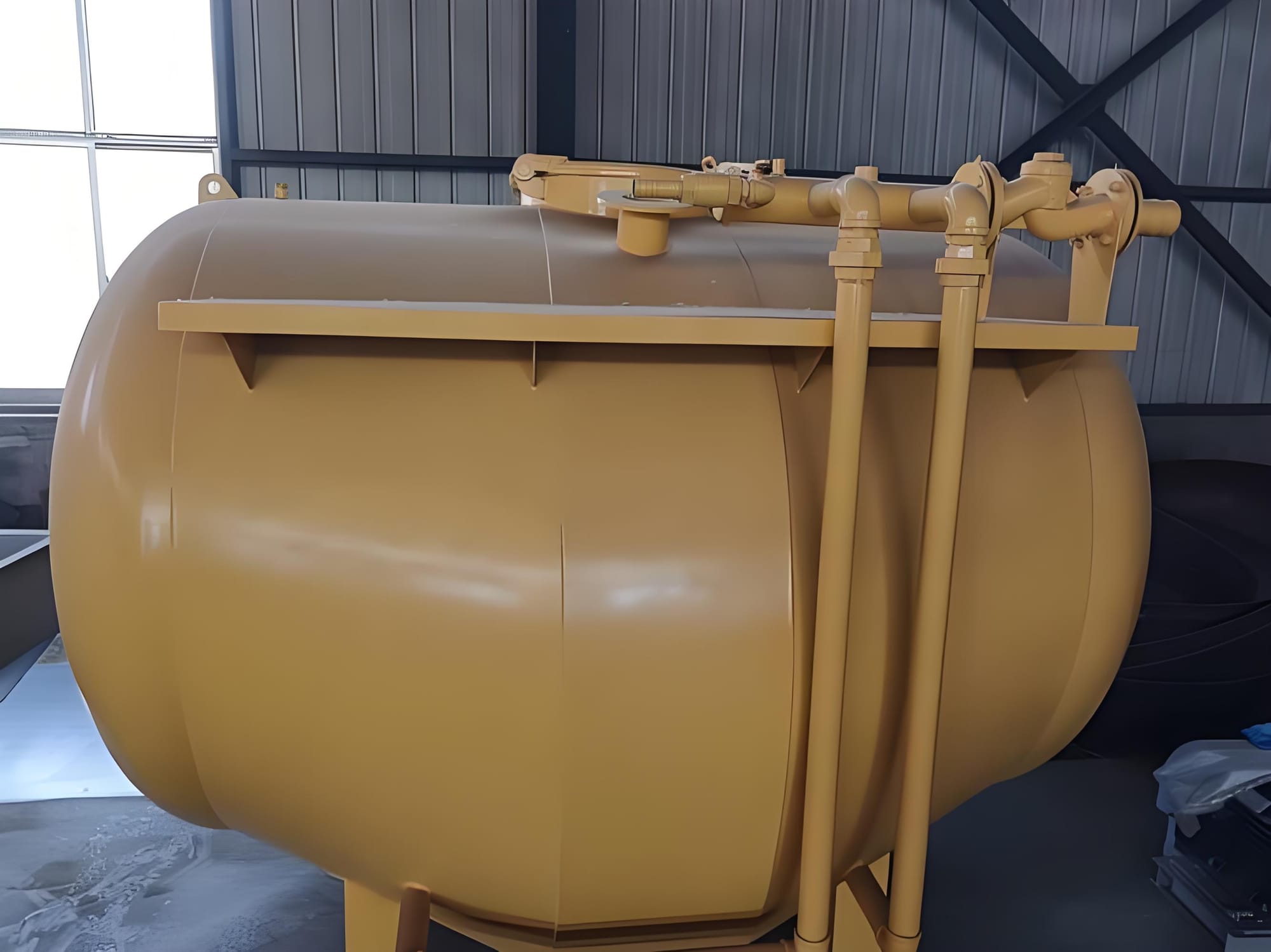
Introduction
In a high-production concrete batching plant, the bulk cement feeder is the unsung workhorse. When a pneumatic cement conveying system operates smoothly, the entire batching sequence stays on schedule. However, when the system encounters a breakdown, production halts completely. A stalled conveyor delays mix trucks, ruins batch consistency, and creates costly project bottlenecks.
Most field failures do not stem from inherent equipment defects. Instead, they are caused by minor air leaks, incorrect valve adjustments, or unnoticed moisture intrusion. This troubleshooting guide provides actionable engineering solutions for the WG5 horizontal double-cone bulk cement feeder and similar systems. It covers root-cause analysis for common bulk cement feeder problems, structural diagnostics, and field-tested maintenance practices designed to maximize equipment uptime and prevent cement conveyor blockage.
How Pneumatic Cement Conveyors Work
Pneumatic cement conveyors utilize dense-phase or dilute-phase fluidization principles within a certified pressure vessel to transfer powder material over vertical and horizontal distances. Understanding the core physics of this process is critical for diagnosing systemic faults in the field.
       [No-Oil Slick Swing Compressor] (0.2 MPa, 5.4 m³/min)
                     │
                     ▼
          ┌──────────────────┐
          │ Main Air Line    │
          └────────┬─────────┘
                   │
         ┌─────────┴─────────┐
         ▼                   ▼
┌─────────────────┐ ┌─────────────────┐
│ Control Valve 7 │ │ Control Valve 8 │
└────────┬────────┘ └────────┬────────┘
         ▼                   ▼
┌─────────────────────────────────────┐
│  Horizontal Double-Cone Tank (5m³)  │
│  [Fluidized Bed / Breathable Cloth] │
└──────────────────┬──────────────────┘
                   │ (Fluidized Cement Powder)
                   ▼
          ┌──────────────────┐
          │ Discharge Port   │◄──── [Secondary Nozzle Valve 5]
          └────────┬─────────┘       (Air-Material Ratio Tuning)
                   │
                   ▼
          ┌──────────────────┐
          │ Discharge Hose   │ (4-Inch Line to Silo)
          └──────────────────┘
The Pressure Vessel Principle
The system revolves around a horizontal, double-cone bipyramid tank structure (such as the 5 m³ WG5 vessel) engineered for a rated working pressure of 0.19 MPa. The tank must maintain structural and pneumatic integrity. When compressed air enters the sealed vessel, the internal pressure acts as the driving energy source required to push heavy material through the discharge piping.
Fluidized Bed Technology
At the bottom of the vessel lies a fluidized bed lined with a specialized, tightly woven breathable canvas cloth. Compressed air enters from the lower air chambers through control valves 7 and 8, forcing its way upward through the canvas. This continuous, evenly distributed upward airflow breaks up the cohesive forces between individual cement particles. It transforms the compacted dry powder into a dynamic, fluid-like state that flows seamlessly toward the discharge suction port.
The Air-Material Mixing Process
Fluidization alone is insufficient to convey the material vertically to a storage silo. The system relies heavily on a critical component known as the secondary nozzle valve (or twice nozzle valve) located near the discharge output line.
The secondary nozzle injects a targeted stream of high-velocity air directly into the discharge pipe downstream of the main discharge valve. This secondary air injection serves two vital engineering purposes:
- It maintains the material-to-air mixing ratio inside the transport hose to keep the powder suspended in the air stream.
- It prevents the dense fluid mass from collapsing and forming an immovable plug inside the piping.
Role of Compressor and Valves
To feed a 5 m³ vessel, the system requires a consistent, clean air source, typically supplied by a specialized no-oil slick swing air compressor (such as the WB5.4/2 model). This compressor must reliably deliver an air displacement of 5.4 m³/min at a rated pressure of 0.2 MPa, powered by an 18.5 Kw motor utilizing a Delta ($\Delta$) connection.
A series of robust mechanical valves govern the pressure loop:
- Control Valves 7 & 8: Route primary air into the front and rear fluidized beds.
- Secondary Nozzle Valve 5: Manages the air-to-material suspension ratio within the discharge stream.
- Discharge Valve 4: Isolates the pressurized tank from the transport line until optimal fluidization pressure is reached.
- Bleeder/Vent Valves 2 & 10: Release internal tank pressure prior to loading cycles.
Common Pneumatic Cement Conveyor Problems
Problem 1: Cement Conveyor Blockage (Pipeline Clogging)
Pipeline blockage is a common and disruptive failure mode in concrete batching plant operations. It occurs when the cement-to-air ratio climbs too high, causing the moving powder to lose velocity and pack into a solid plug.
Symptoms
- A sudden, sharp spike on the air compressor pressure gauge toward the 0.2 MPa relief limit.
- A sudden drop in material flow sound inside the pipeline (loss of the characteristic rushing sand sound).
- The delivery hose becomes heavy and rigid due to packed material.
Possible Causes
- Opening discharge valve 4 before the vessel reaches its operational fluidization pressure of 0.19 MPa.
- Setting secondary nozzle valve 5 too low, resulting in insufficient air to keep the material suspended.
- Introducing un-screened cement containing wet material clumps or foreign debris (such as shredded paper bags).
- Excessive bends or sharp kinks in the delivery hose layout (violating the two-bend maximum rule).
Diagnosis Steps
- Verify if the line weight has significantly increased at a localized section.
- Place an ear safely near the hose line to check for the absence of high-velocity powder friction sounds.
- Check the compressor gauge. If it reads near maximum pressure while zero material enters the silo, a total line blockage is confirmed.
Solutions
- Pneumatic Purge Method: Immediately close discharge valve 4 and lower operation valves 7 and 8. Fully open secondary nozzle valve 5 to direct the compressor's entire air volume into the transport line to blow the clog clear.
- Mechanical Intervention: If the pneumatic purge fails, shut down the air compressor immediately. Open bleeder valves 2 and 10 to completely depressurize the vessel. Disconnect the affected hose coupling and manually clear the compacted cement plug using mechanical clean-out rods.
*Diagnostic Protocol for Abrupt Backpressure Spikes:
When the control room monitors a sudden pressure jump exceeding 0.22 MPa (in dense-phase conveying), do not immediately increase blower frequency—this risks compressing the blockage into a rock-hard plug.
- Check Air-to-Material Ratio: Cement moisture exceeding 0.5% causes instant agglomeration. Inspect the water-separator/refrigerated air dryer immediately. If the pressure gauge near the pressure vessel (fluidized tank) fluctuates rapidly, the fluidizing cloth/membrane is likely blinded by hardened cement crusts.
- Localized Tap Test: Use a dead-blow hammer to tap along the 90-degree long-radius bends (typically schedules 40/80 carbon steel with ceramic linings). A dull, heavy thud indicates the exact location of the dune-formation clog.
Problem 2: Low Conveying Pressure
When a pneumatic cement conveying system cannot build or sustain its nominal 0.19 MPa operating pressure, the air velocity drops below the minimum required transport threshold, leading to poor discharge rates and eventual line blockages.
Compressor Problems
- Slipping Drive Belts: Check the V-belt transmission system (e.g., B-1600 × 5 belts). Loose belts slip under high load, preventing the air compressor from reaching its rated output.
- Choked Intake: A heavily dust-choked air filter element restricts the intake airflow, decreasing the displacement rate below 5.4 m³/min.
Air Leakage Points
- Loading Hatch Seal Failure: Powder accumulation on the rim of loading hatch 3 degrades the seal ring gasket. This creates an audible high-pressure air leak that bleeds off vessel energy.
- Pipe Joint Degradation: Damaged couplings along the 4-inch pipeline bleed air pressure continuously.
Valve Issues
- Internal Leaking: Worn valve seals allow high-pressure air to escape into atmospheric vent lines or back into non-active piping circuits.
Mitigating Blow-by Gas in Twin-Shaft Mixer Feeding Systems:
Because cement is highly abrasive, the clearance between the rotary airlock rotor blades and the housing must not exceed 0.15 mm.
- The Blow-by Effect: Air leaking upward through excessive rotor clearance fluidizes the incoming cement in the hopper, causing bridging (ratholing) and a drastic drop in mass flow rate.
- Shaft Seal Troubleshooting: If cement dust is blowing out of the shaft ends, the packing gland is shot. Do not just tighten the gland nuts (which scores the shaft); transition to braided PTFE-Graphite packing combined with a 0.2 MPa positive air-purge system to create an active air barrier that keeps abrasive particles out of the bearing race.
Problem 3: Slow Cement Discharge Rates
Slow material discharge extends batching cycle times, limits plant productivity, and increases the wear and tear on the air compressor components.
+-------------------------------------------------------------------------+
|                       SLOW CEMENT DISCHARGE                             |
+-------------------------------------------------------------------------+
                               │
            ┌──────────────────┴──────────────────┐
            ▼                                     ▼
┌───────────────────────┐             ┌───────────────────────┐
│   Material Moisture   │             │ Fluidized Bed Faults  │
└───────────┬───────────┘             └───────────┬───────────┘
            │                                     │
            ▼                                     ▼
• Caking on breathable cloth          • Loose canvas bypasses air
• High frictional resistance          • Torn cloth dumps powder
• Reduced active flow path            • Complete loss of fluidization
Material Moisture
- Even minor moisture inside the vessel causes cement to cake along the internal double-cone slopes. This caking chokes the path to the absorbing port and reduces the active material flow rate.
Fluidized Bed Faults
- If the breathable canvas cloth becomes torn or loose, compressed air bypasses the material mass entirely. Instead of fluidizing the cement powder, the air creates a localized path of least resistance, leaving the bulk material densely compacted at the bottom of the tank.
Incorrect Air Adjustment
- The Mixing Ratio Mismatch: If an operator opens secondary nozzle valve 5 too wide during the primary discharge phase, it starves the fluidized bed of air. This causes the material to settle in the tank while clean air blows out the discharge line. Conversely, closing valve 5 too much starves the transport line, causing high frictional resistance and a slow delivery rate.
Problem 4: High Residual Cement After Unloading
A high material residual rate (exceeding the standard limit of < 0.4%) indicates inefficient tank clean-out, reducing effective batch capacity and risking internal product crusting.
Installation Issues
- Improper Ground Leveling: If the vessel stand is not mounted on a level foundation, the internal gravity-fed slope toward the central discharge suction port is disrupted. Cement pools in the unaligned low spots of the double-cone floor, causing high residual material.
Internal Contamination
- Leaving the tank uncleaned after processing a damp batch creates a hardened cement crust inside the tank. This crust disrupts air distribution across the fluidized bed canvas and traps dry powder during subsequent unloading cycles.
Operating Mistakes
- Skipping the Clearing Phase: Operators often shut down the system as soon as the pressure drops, without running a clean-out cycle.
- Correct Engineering Practice: When vessel pressure falls to 0.13 MPa, control valves 7 and 8 must be modulated independently to concentrate air velocity and sweep residual material from both ends of the tank.
Technical Diagnostic Reference Table
| Symptom | Possible Root Cause | Field Solution |
Pipeline pressure suddenly spikes to 0.2 MPa | Delivery hose blockage/plugging | Close discharge valve 4; fully open secondary nozzle valve 5 to clear plug |
Tank pressure stays $< 0.13$ MPa during start | Absorbing suction port blocked by debris | Stop compressor, vent pressure, open hatch 3, and clear object from tank floor |
Audible air hiss at the loading hatch | Cement dust buildup on seal ring or damaged gasket | Depressurize tank completely, clean seal surface, or replace damaged gasket |
Low compressor displacement volume | Slipping V-belts or choked intake filter | Tension belts to 8 mm deflection at 5 kg load; clean air filter element |
Material flow slows down with low pressure | Fluidized bed canvas cloth torn or loose | Drain tank completely, inspect canvas liner, and secure or replace cloth |
Preventive Maintenance Checklist
A structured preventive maintenance schedule is essential for the reliability of bulk cement feeders and concrete batching plant equipment.
Daily Inspection (Pre-Shift Checklist)
- [ ] Compressor Lubrication: Check oil levels in the compressor crankcase and grease all external rotation bearings.
- [ ] Valve Cleaning: Wipe accumulated cement dust away from valve stems, actuators, and handwheels.
- [ ] Hardware Torque: Inspect air line flange bolts and structural mount connections for vibration-induced loosening.
- [ ] Line Integrity: Check all flexible rubber transport lines for external wear, soft spots, or localized flat sections.
- [ ] Fluidized Bed Verification: Peer into the empty tank to verify that the fluidized bed area is clear of foreign stones or crusts.
- [ ] Hatch Inspection: Check the loading hatch cover's locking claws and clamping mechanisms for structural bending.
Weekly Inspection
- [ ] Air Filter Service: Remove the air compressor intake filter element and blow it clean with low-pressure shop air. Clean more frequently in high-dust batching environments.
- [ ] Seal Integrity: Inspect the high-pressure rubber seal profile inside the loading hatch cover for deep gouges or structural compression sets.
Bi-Weekly & Monthly Maintenance
- [ ] Belt Tensioning (Every 2 Weeks): Test the V-belt drive tension. Apply a 5 kg force directly to the center of the belt's slack side; the measured belt deflection must equal exactly 8 mm.
- [ ] Safety Valve Calibration (Monthly): Bench-test or field-verify the spring-loaded primary safety valve. It must pop open and vent excess pressure precisely at 0.195 MPa.
Semi-Annual Maintenance (Every 6 Months)
- [ ] Valve Overhaul: Disassemble all primary inline control valves and inspect internal gate disks, seats, and seals for abrasion from abrasive cement dust.
- [ ] Hatch Drive Lubrication: Remove the heavy threaded screw sleeve from the center of loading hatch cover 3. Inspect both the inner drive screw rod and sleeve threads for wear, then pack the entire internal cavity with clean, high-temperature industrial grease.
- [ ] Moisture Abatement: Verify that the entire operator platform area and air tank lines remain dry and free of standing water to preserve the permeability of the fluidizing bed fabric.
Pneumatic Conveyor PM Schedule
| Interval | Component | Action & Standard | Critical Limit |
|---|---|---|---|
| Every Shift | Roots Blower | Listen for gear whining; check oil sight glass levels and V-belt tension. | Bearing temp > 85°C |
| Weekly | Baghouse Filter | Verify pulse-jet cleaning pressure; monitor differential pressure (DP) gauge. 。 | DP > 1500 Pa after pulse |
| Monthly | Conveying Elbows | Perform ultrasonic thickness testing (UT) at the outer radius of velocity impact zones. | Wall loss > 60% of nominal |
Safety Guidelines
Pneumatic bulk material handling involves high-pressure containment vessels and high-velocity abrasive dust streams. Ignoring proper safety protocols can lead to catastrophic equipment damage or severe personal injury.
Pressure Vessel Integrity
Never perform structural maintenance, welding repairs, or bolt tightening while the vessel is under load. If a pressure leak develops along the loading hatch seal during a discharge run, do not attempt to force the hatch tighter. Immediately isolate the compressor power source and wait for the system to depressurize completely before attempting adjustments.
Double-Check Air Release Procedure
Prior to turning the loading hatch handwheel or unlocking the clamping assembly, operators must open right-side bleeder valve 2 and verify that zero air emerges from the exhaust line.
If the right-side valve shows no discharge but the vessel still feels pressurized, the left-side pressure release pathway or its breathable cloth filter shroud may be completely choked with compacted cement dust. Operators must wait for the trapped residual air to bleed down completely before breaking the hatch seal to prevent a dangerous pressure release.
+------------------------------------------------------------+
|               HATCH OPENING SAFETY CHECK                   |
+------------------------------------------------------------+
                              │
                              ▼
                 Open Right Bleeder Valve 2
                              │
            ┌─────────────────┴─────────────────┐
            ▼                                   ▼
   [ Air Rushes Out ]                  [ No Air Outflow ]
            │                                   │
            ▼                                   ▼
  Wait for pressure to               Open Right Valve 10 to
  drop to zero completely.           double-check safety.
            │                                   │
            └─────────────────┬─────────────────┘
                              │
                              ▼
               Is Hatch Safely Depressurized?
                              │
            ┌─────────────────┴─────────────────┐
            ▼                                   ▼
         ( Yes )                             ( No )
            │                                   │
            ▼                                   ▼
   Safe to open hatch.               Left release unit is blocked.
                                     Do NOT force hatch open.
                                     Wait for complete bleed down.
Loading Cover Operation
When securing loading hatch 3, use smooth, steady torque on the manual locking levers. Never use cheater bars, heavy hammers, or impact tools on the valve handles or handwheels. Applying excessive force deforms the internal alignment plates, ruining the airtight seal and binding the assembly.
Operator Protection Boundaries
During active air fluidization and discharge cycles, all field crew members must maintain a physical safety distance of at least 1 meter away from the loading hatch perimeter and high-pressure pipe junctions.
Conclusion
Pneumatic cement conveyor reliability depends on maintaining a proper balance between high-volume airflow and fluid material delivery. Most field failures, such as line blockages or low conveying pressure, are directly caused by air leaks, moisture contamination, or improper valve adjustments.
Concrete plants can minimize unscheduled downtime by implementing a strict preventive maintenance program. This includes verifying drive belt tension, keeping air filters clean, and monitoring safety valve calibration. Properly trained operators who understand correct valve sequencing and safe pressure release procedures can ensure efficient material transfer and reliable long-term equipment operation.
FAQ Section
Q: Why does a pneumatic cement conveyor block?
A: Blockages typically occur when an operator opens the primary discharge valve before the vessel reaches its full fluidization pressure (0.19 MPa). It can also be caused by incorrect setting of the secondary nozzle valve, which starves the pipeline of transport air, or by moisture intrusion that clumps the powder.
Q: What is the purpose of the secondary (twice) nozzle valve?
A: The secondary nozzle valve controls the mixing ratio of cement powder and air inside the transport pipe. It introduces high-velocity air downstream of the vessel to keep the fluidized cement suspended, preventing it from settling out and plugging the transport line.
Q: How can you tell if a delivery hose is blocked without opening it?
A: A blocked hose is indicated by a sudden jump in the compressor pressure gauge toward its maximum limit (0.2 MPa) combined with an immediate loss of material rushing sounds inside the line. Physically, the blocked section of the hose will become heavy and rigid due to the packed cement.
Q: What should I do if the tank pressure will not rise above 0.13 MPa?
A: If pressure fails to build, shut down the air compressor and check for air leaks around the loading hatch seal or pipe couplings. If no leaks are found, the internal suction port may be blocked by foreign debris, or the fluidized bed canvas cloth may be torn or loose, allowing air to bypass the material.
Q: How often should the air compressor drive belts be checked?
A: Drive belts should undergo a tension inspection every two weeks. Correct adjustment requires that when 5 kg of pressure is applied directly to the midpoint of the belt's slack side, the physical deflection measures exactly 8 mm.
Q: Why is it dangerous to open the loading hatch even if the pressure gauge reads zero?
A: If the primary internal release path or its cloth filter shroud becomes heavily caked with cement dust, it can trap high-pressure air inside the vessel even if the external gauge shows zero. Opening the hatch under these conditions can cause a violent pressure release. Always verify that both bleeder valves show no air outflow before opening the hatch.
Request Technical Blueprints & Factory Quotes
Submit your machinery parameters below. Connect directly with verified, certified heavy industrial manufacturers to receive custom foundation drawings, layout schematics, and direct-from-factory pricing.