
Concrete Batching Plant Common Failures and Troubleshooting Guide (Motor, Compressor, Mixer & Hydraulic System)
A technical manual for diagnosing and repairing critical failures in industrial twin-shaft concrete mixers. Learn step-by-step procedures to resolve main motor stalls, pneumatic compressor cycling, and hydraulic gate malfunctions.

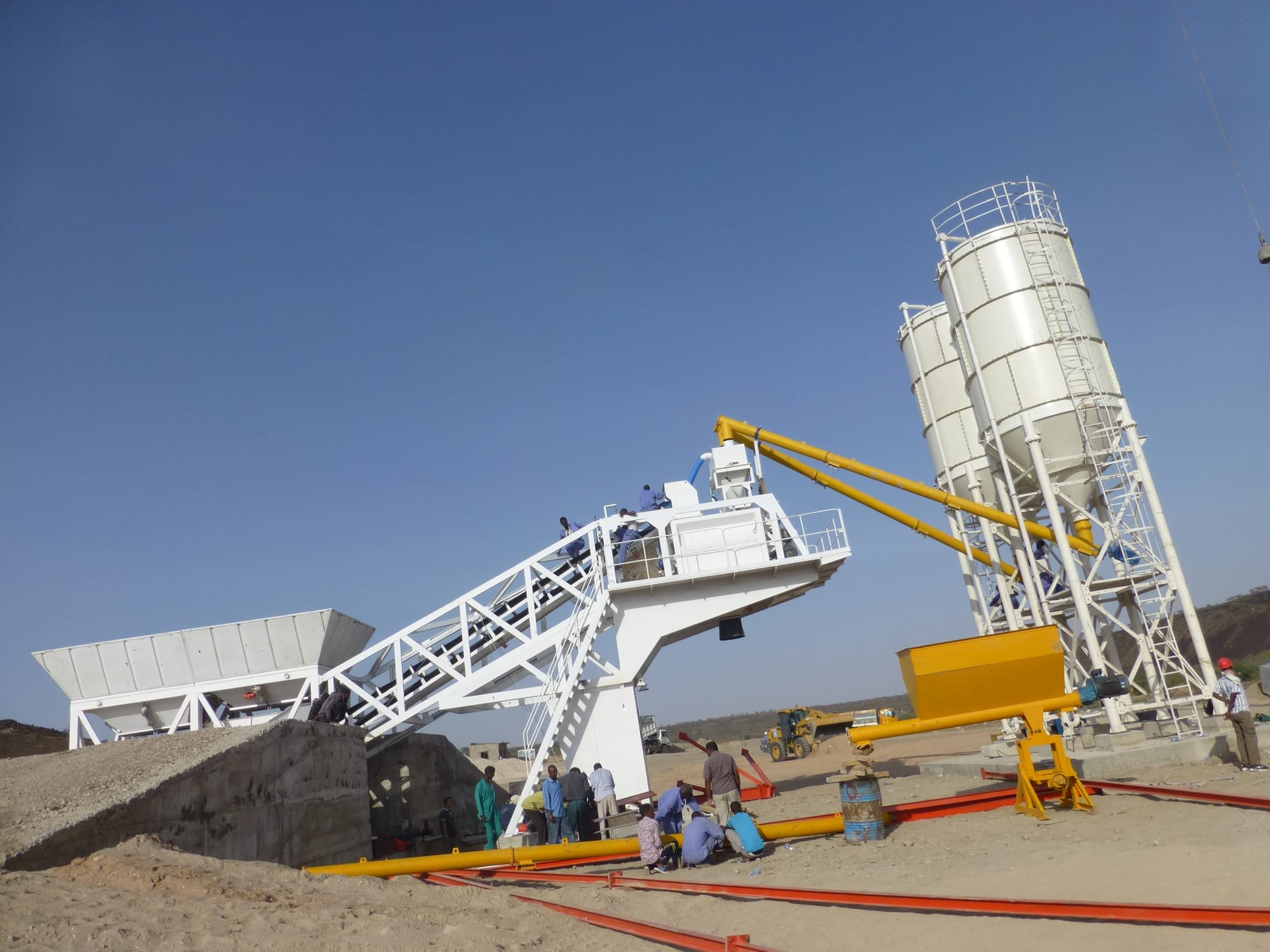
Problem Description (Symptoms)
Field failures in concrete batching plants typically present as discrete mechanical-electrical-hydraulic coupling faults. The most common operational symptoms include:
- Main mixer motor fails to start or emits continuous low-frequency humming (“motor stall hum”) during startup.
- Air compressor short-cycles (frequent start/stop) under no obvious production change.
- Mixer discharge gate fails to open or close, resulting in blocked discharge cycle or incomplete batching.
- Mixer “bogging” / material overloading with abnormal current spike and belt slippage odor.
- Shaft build-up / concrete adhesion on mixing shafts (shaft coating / axial buildup) leading to rising load torque and current overload.
These failures are typically progressive. Early-stage indicators are often ignored until full production interruption occurs.

Problem Description: Twin-Shaft Mixer Motor Fails to Start (such as industrial JS1500 or JS3000 series)
During the concrete plant startup sequence, the primary mixer motor either fails to rotate completely or struggles to crank while emitting a distinct, heavy magnetic humming/buzzing sound.
Emergency Protocol: Stop the sequence immediately. Disconnect the main breaker and lock out/tag out (LOTO) the power supply before manual inspection to prevent winding burnout.
Step-by-Step Diagnostic Procedures
Step 1: Motor Junction Box Inspection
- Open the terminal junction box on the mixer motor frame.
- Use a digital multimeter to measure the incoming three-phase line-to-line voltage.
- Check for single-phasing (loss of phase) or excessive voltage drop across terminals (U1, V1, W1).

Step 2: Control Cabinet Circuit Breaker Diagnostics
If the junction box readings are abnormal or a phase is missing:
- Open the main electrical control cabinet.
- Measure the output terminals of the molded case circuit breaker (MCCB) dedicated to the mixer motor.
- Verify if the phase loss originates from bad breaker contact points.

Step 3: Main Grid Power Verification
If the breaker output remains faulty:
- Probe the incoming main grid supply terminals at the cabinet's primary isolator.
- Determine if the issue is a utility-side grid fault or a plant-wide power quality anomaly.
Root Cause Analysis
- Utility Grid Malfunction: Phase imbalance, complete phase loss, or severe voltage drops originating from the main power grid supply lines.
- Contact Failure in MCCB: Pitted, oxidized, or misaligned internal contacts inside the main circuit breaker, blocking a single phase under load conditions.
- Internal Motor Fault (Low Probability): Internal short-circuits, stator winding insulation breakdown, or mechanical rotor seizure.

Problem Description:Air compressor short-cycles (frequent start/stop)
The air compressor supplies compressed air to the batching plant pneumatic distribution network.
This system actuates pneumatic aggregate bin gates, hopper discharge doors, and weighing scale discharge valves.
Frequent start-stop cycling indicates abnormal air demand stability or control logic failure.
This condition accelerates wear on the compressor pump head and motor contactors.
Expected operating behavior:
- Stable pressure build-up
- Controlled cut-in / cut-out cycle
- Minimal restart frequency under sealed system
Fault indicators:
- Compressor starts at short intervals
- Audible air leakage (“hissing” sound along pipelines)
- Rapid pressure drop in storage tank
- Unstable switching between cut-in and cut-out states
Safety Protocol:
Implement Lockout/Tagout (LOTO) procedures and disconnect primary power before inspection. Depressurize the air receiver tank completely.
Step-by-Step Diagnostic Procedures
- Air Leak Inspection Across Pneumatic Network
Inspect all compressed air pipelines from compressor outlet to end actuators.
Focus on pneumatic push-in fittings, threaded couplers, and manifold joints.
Detect leakage via audible “hissing” or pressure decay zones. - Storage Tank Integrity Check
Inspect air receiver tank weld seams and drain valve assembly.
Confirm no continuous pressure loss when system is idle. - Differential Pressure Switch Assembly Evaluation
Check for unstable switching behavior or contact wear.
Verify cut-in/cut-out consistency under load conditions. - Pressure Switch Calibration Test
Adjust setpoints and observe cycling stability.
Replace unit if response delay or drift is detected.
Root Cause Analysis
- Degraded pneumatic seals at hose couplers
- Thread sealant failure on pipe fittings
- Micro-leakage in air receiver tank drain valve
- Faulty differential pressure switch assembly contact wear
- Incorrect cut-in/cut-out pressure differential setting
- Excessive system leakage increasing compressor duty cycle

Technical Guide: Pressure Switch Adjustment Methodology
1. System Pressure Adjustment
- Rotate pressure adjustment screw clockwise
→ Increases both cut-in and cut-out pressure thresholds - Rotate counterclockwise
→ Decreases both cut-in and cut-out pressure thresholds
Effect:
Maintains fixed differential while shifting overall operating range.
2. Differential Pressure Adjustment
- Rotate differential adjustment screw clockwise
→ Cut-out pressure increases, cut-in remains constant
→ Expands operating pressure band - Rotate counterclockwise
→ Cut-out pressure decreases, cut-in remains constant
→ Narrows operating pressure band
Effect:
Directly controls compressor restart frequency and cycling behavior.
Preventative Maintenance Checklist
- Conduct weekly leak detection across pneumatic distribution lines
- Replace aged pneumatic seals and thread sealants during scheduled shutdowns
- Verify differential pressure switch assembly calibration every 3 months
- Drain air receiver tank condensate daily to prevent internal corrosion and micro-leaks

Problem Description:Mixer discharge gate fails to open or close
The mixer discharge gate assembly is driven by an independent motor-driven hydraulic power unit (HPU).
Hydraulic cylinders control opening and closing through directional oil flow regulation.
Failure symptoms include:
- Discharge gate remains fully closed or fully open
- Intermittent movement with hydraulic delay response
- Abnormal pump noise or no hydraulic pressure build-up
- Solenoid directional control valve non-responsive actuation
- Hydraulic pressure loss under load
Emergency safety protocol:
Lock out electrical power supply before inspection.
Release residual hydraulic pressure before touching valve block or cylinder lines.
Typical system architecture includes:
- Independent motor-driven hydraulic power unit (HPU)
- Solenoid directional control valve manifold
- Hydraulic pressure relief valve adjustment bolt
- Double-acting hydraulic cylinder (gate actuator)
- PLC-based control circuit and relay interface

Step-by-Step Diagnostic Procedures
- Verify electrical supply to hydraulic drive motor
Confirm motor power input and contactor engagement.
Check for phase loss or overload trip condition. - Inspect hydraulic power unit (HPU) operation
Listen for pump rotation noise stability.
Measure system pressure at test port.
No pressure indicates pump or motor failure. - Check solenoid directional control valve excitation
Confirm solenoid coil voltage activation.
Test coil resistance integrity.
Inspect valve spool for mechanical jamming. - Inspect hydraulic pressure relief valve setting
Verify hydraulic pressure relief valve adjustment bolt torque.
Incorrect setting causes premature pressure bypass. - Evaluate hydraulic cylinder performance
Check for external oil leakage at rod seal.
Test internal piston seal bypass (internal leakage).
Observe pressure drop under static load holding test. - Diagnose control circuit logic output
Verify PLC output signal to solenoid valve.
Inspect relay contacts and wiring continuity.
Check emergency stop interlock status.
Root Cause Analysis
- Hydraulic pump motor not energized due to electrical failure
- Solenoid directional control valve coil not energized or spool jammed
- Hydraulic cylinder external leakage or internal piston seal bypass (internal leakage)
- Hydraulic pressure relief valve misadjustment causing insufficient system pressure
- Control circuit failure in PLC output module or relay interface
- Contaminated hydraulic oil causing valve spool sticking or flow restriction
Preventative Maintenance Checklist
- Maintain hydraulic oil cleanliness level below ISO NAS 8 standard
- Perform monthly solenoid valve coil voltage and resistance testing
- Inspect hydraulic cylinder rod seals for early-stage leakage traces
- Recalibrate hydraulic pressure relief valve adjustment bolt every 3 months

Problem Description:Mixer “bogging” / material overloading
The mixer experiences a Concrete Mixer Overload Jam (Twin-Shaft Stall Condition) when material viscosity exceeds torque capacity.
Immediate symptoms:
- Abnormal knocking noise from main drive motor
- Drive motor overcurrent trip / spike in amperage readings
- Drive belt frictional slippage causing severe thermal scorching odors
- Reduced or blocked rotation of mixing shafts
- PLC alarm triggered in central control room
Electrical monitoring indicators:
- Motor current exceeds rated load threshold
- Voltage stability remains normal while torque demand spikes
- Belt drive efficiency drops under transient load shock
Emergency protocol:
Stop the mixer immediately under overcurrent trip condition.
Do not restart until mechanical resistance is confirmed clear.
Step-by-Step Diagnostic & Recovery Procedures
- Isolate power and secure lockout condition
Confirm full shutdown at control cabinet.
Verify zero-energy state before inspection hatch opening. - Inspect mixing chamber via inspection hatch
Check for hardened concrete agglomeration or material bridging.
Identify shaft immobilization points. - Operate manual discharge gate system
Open discharge gate to release trapped batch material.
Confirm gravity discharge flow clearance. - Switch motor control panel to jog mode
Pulse the electric motor in short bursts.
Apply controlled torque release to dislodge jammed mass.
Monitor amperage rebound during each pulse cycle. - Inspect V-belts and drive transmission system
Check belt glazing, cracking, and thermal damage.
Detect slippage marks on pulley grooves.
Replace belts if thermal deformation is present. - Verify aggregate flow and batching sequence integrity
Confirm feeder discharge timing alignment.
Check cement, water, and aggregate scale synchronization.
Root Cause Analysis
- Aggregate discharge imbalance from intermediate silo or weighing bins
- Cement, water, or aggregate batching sequence misalignment
- Severe V-belt wear and tension loss causing torque transfer failure
- Mixing shaft partial seizure due to hardened concrete accumulation
- Aggregate moisture content variance necessitating immediate water-cement mix design compensation
- Delayed discharge from weigh hoppers causing overloading in initial mixing phase
Preventative Maintenance Checklist
- Calibrate aggregate moisture sensors weekly under variable weather conditions
- Inspect and retension V-belts every 250 operating hours
- Validate batching sequence timing across all weigh systems monthly
- Remove hardened residue from mixing chamber after every production shift

Problem Description:Shaft build-up / concrete adhesion on mixing shafts (shaft coating / axial buildup)
Concrete Buildup on Mixer Shafts (Shaft Incrustation / Shaft Scaling) develops when residual cement paste hardens on rotating elements.
Progressive symptoms:
- Increased parasitic mechanical load leading to drive motor amperage spikes
- Abnormal rise in baseline current draw under nominal batching volume
- Accelerated V-belt wear due to continuous overload torque
- Reduced mixing efficiency and shaft rotational resistance
- Visible diameter expansion of mixing shafts during inspection

Electrical and mechanical indicators:
- Motor current exceeds historical baseline by 10–30%
- Torque demand increases without proportional batch volume change
- Belt drive temperature rises during continuous operation cycles
Operational warning:
Sustained operation under shaft incrustation accelerates gearbox and bearing fatigue failure.
Step-by-Step Diagnostic Procedures
- Establish electrical lockout and isolation
Disconnect main power supply.
Confirm zero-energy state at control cabinet. - Log baseline motor amperage data
Compare real-time current against historical operating curve.
Identify abnormal torque escalation patterns. - Open inspection hatch safely
Secure mechanical access points.
Ensure no residual rotation risk exists. - Visually inspect shaft surface condition
Check for hardened concrete layer adhesion.
Measure apparent shaft diameter increase.
Confirm asymmetric scaling along mixing arms. - Evaluate drive system stress indicators
Inspect V-belt tension and glazing condition.
Detect thermal discoloration or slippage marks.
Check bearing vibration signature anomalies.
Root Cause Analysis
- Misaligned water discharge nozzle orientation/geometry causing uneven wash coverage
- Optimizing batching sequence logic within the plant automation software not implemented
- Inadequate post-batch washout cycles after production completion
- Extended idle time between batching cycles allowing cement hydration on shaft surfaces
- High cement content mix designs without proportional cleaning compensation cycle
Corrective Actions & Engineering Solutions
- Reposition water spray system to ensure full shaft coverage
- Adjust water discharge nozzle orientation toward shaft rotation plane
- Reprogram batching automation sequence for optimized water-first dispersion timing
- Introduce mandatory wash cycle after each production batch
- Reduce idle interval between mixing cycles below hydration threshold window
Mechanical intervention:
- Perform manual descaling of shaft incrustation layers
- Use mechanical scraping tools for hardened concrete removal
- Inspect shaft alignment after cleaning cycle completion
Preventative Maintenance Checklist
- Install automatic high-pressure washout ring system on mixing chamber
- Enforce mandatory manual descaling intervals and mechanical chipper cleanouts
- Calibrate batching software sequence logic quarterly
- Monitor motor amperage drift trend for early-stage buildup detection
The technical parameters, safety workflows, and adjustment procedures detailed in this guide comply with international industrial standards for concrete production machinery, including ISO 19720 (Building construction machinery and equipment — Concrete batching plants) and regional manufacturing guidelines (SICOMA, SANY, Putzmeister).
Request Technical Blueprints & Factory Quotes
Submit your machinery parameters below. Connect directly with verified, certified heavy industrial manufacturers to receive custom foundation drawings, layout schematics, and direct-from-factory pricing.