
Concrete Batching Plant Troubleshooting: Fixes for 4 Common Mixer Failures (Twin-Shaft JS Series)
A practical troubleshooting guide for JS series twin-shaft concrete mixers, covering common mechanical, hydraulic, discharge, and drive system failures in concrete batching plants.

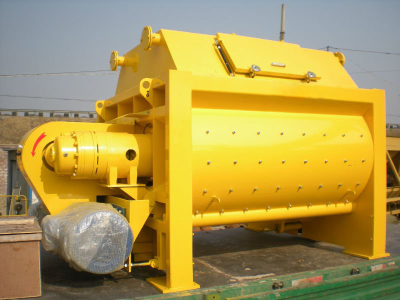
In high-volume concrete production environments, twin-shaft mixers such as the JS1000, JS1500, and JS3000 operate under continuous mechanical stress. Heavy loads, abrasive aggregates, hydraulic systems, and frequent start-stop cycles can accelerate wear on critical components.
When a mixer failure occurs, relying only on general equipment manuals is often not enough. Maintenance teams need practical troubleshooting procedures that help identify the root cause quickly, reduce downtime, and prevent secondary damage.
This guide provides a field-oriented troubleshooting approach for common twin-shaft mixer failures, combining equipment operation experience with practical maintenance methods used in concrete batching plants.
For ready-mix concrete (RMC) plants and large construction projects, the twin-shaft JS series mixer is one of the most critical components in the production line. A mixer stoppage during production can interrupt the batching process, delay deliveries, and create additional maintenance costs. If concrete remains inside the mixer after shutdown, the material may harden depending on factors such as ambient temperature, cement type, mix design, and cleaning procedures, potentially causing difficult and expensive removal work.
Based on common failure patterns observed in twin-shaft concrete mixers, this troubleshooting guide focuses on four frequently reported problems, including mechanical wear, hydraulic faults, discharge gate issues, and drive system failures.
Each section provides practical inspection steps, possible causes, and recommended corrective actions that operators and maintenance technicians can use to diagnose problems more efficiently.
1. Main Mixer Motor Fails to Start or Emits a Heavy Humming Sound
🚨 Immediate Field Action (Safety Protocol)
If the motor emits a low-frequency hum but fails to rotate when you press the start button, cut the power within 3 seconds! (In our team’s 15 years of RMC plant commissioning, we have seen over 40 standard motors burn out simply because operators hesitated for 10 seconds. Our golden rule on-site is: If it hums and won't turn, kill the power by count three) Continuous current under a locked-rotor state will burn out the stator windings rapidly.

Field-Engineer Diagnostic Sequence
| Step | Component to Inspect | Real-World Action & Evaluation |
|---|---|---|
| Step 1 | Main Control Cabinet | Do not disassemble the motor junction box first. Open the electrical cabinet and check the Molded Case Circuit Breaker (MCCB). Look closely at the Thermal Overload Relay . If the trip indicator is up, the motor overloaded. Wait 5 minutes for it to cool down, then press the reset button. |
| Step 2 | Contactor & Line Voltage | Measure the three-phase incoming and outgoing voltage across the main contactor using a multimeter. If a phase is missing, you have a Single-Phasing issue. Inspect the contactor contacts for severe pitting, oxidation, or mechanical binding. |
| Step 3 | Mechanical Inspection | Execute full Lockout-Tagout (LOTO) protocols. Open the mixer inspection cover. Check if oversized aggregate, trapped rebar, or hardened concrete chunks from a previous shift are mechanically locking the mixing blades. |
Root Cause Analysis
- Severe Contact Pitting: Frequent high-current switching creates arcs that destroy a single contact pole, causing the motor to single-phase upon start.
- Chamber Jamming: Inadequate batcher screening allows oversized rocks to bypass the grid and wedge directly between the mixing blade and the liner plate.

2. Air Compressor Reciprocates Frequently (Short-Cycling)
The pneumatic system drives critical gates, including aggregate bin doors, aggregate scales, and discharge butterfly valves. An air compressor that cycles on and off every 1 to 2 minutes accelerates contactor pitting and pump wear.
Dynamic Field Diagnostics
- Static Pressure Drop Test: Observe the air receiver tank pressure gauge when the plant is completely idle (no pneumatic gates operating). If the pressure drops by more than 0.5 Bar per minute, a severe downstream leak is present.
- The Soap-Water Spray Method: Pressurize the system and spray a liquid soap solution onto push-in fittings, the FRL unit (Filter-Regulator-Lubricator), pneumatic valve exhaust ports, and the tank drain valve. Look for growing bubbles. Continuous bubbling at a valve exhaust port indicates a worn internal spool seal.
- Pressure Switch Differential Adjustments: Locate the mechanical pressure switch on the compressor pump housing.
How to Properly Adjust a Mechanical Pressure Switch
- Main Pressure Adjustment Bolt (Large Screw): Turning this clockwise increases both the cut-in and cut-out pressure simultaneously, shifting the entire operating pressure range upward.
- Differential Pressure Bolt (Small Screw): Turning this clockwise increases the cut-out pressure while keeping the cut-in pressure constant. This widens the pressure differential, directly reducing the compressor's cycling frequency.
Preventive Maintenance Schedule
- Daily Condensate Drainage: Manually open the drain valve at the bottom of the air receiver tank at the end of every shift. Purging moisture prevents water from entering the solenoids and causing valve seizure.
- Weekly Leak Audits: Spend 10 minutes during lunch shutdowns checking major pneumatic manifolds with soapy water.

3. Discharge Gate Fails to Open or Lacks Hydraulic Pressure
Most commercial batching plants utilize an independent Hydraulic Power Unit (HPU) paired with double-acting hydraulic cylinders to operate the discharge gate.

Troubleshooting Logic Chain
- Check Oil Level and Fluid Quality: Inspect the HPU sight gauge. Low oil levels introduce air into the pump, causing severe cavitation and loud, high-pitched whining. Verify if the oil is milky white (water contamination) or dark black (thermal degradation).
- Verify Main System Pressure: Trigger the discharge gate opening switch and monitor the HPU pressure gauge. If pressure reads zero or stays very low, turn the adjustment bolt on the Pressure Relief Valve clockwise. If the pressure fails to respond, the valve spool is likely jammed open by particulate contamination.
- Solenoid Directional Valve Manual Override: Use a small screwdriver to press the manual override pins on either side of the solenoid directional valve. If the gate cycles normally via the manual pins, your hydraulic system is mechanically sound; the fault lies in a burned solenoid coil or a failed PLC output relay.
- Cylinder Bypass (Internal Leakage) Test: Extend the cylinder completely to one end of its stroke, shut off the HPU, and disconnect the hydraulic hose from the opposite, unpressurized port. Restart the HPU and apply pressure to keep the cylinder extended. If oil streams out of the open port, the internal piston seal has failed, allowing fluid to bypass the piston.
Critical System Benchmarks
- Thermal Monitoring: Operating oil temperatures must remain below 60°C (140°F).
- Fluid Replacements: Flush and replace anti-wear hydraulic oil every 2,000 operating hours (typically ISO VG 46 for summer, ISO VG 32 for winter). Clean the suction strainer during every fluid change.

4. Mixer Shaft Buildup and Total Stalling (Shaft Encrustation & Overloading)
The Phenomenon of Shaft Encrustation
When cement slurry accumulates on the mixing shaft and hardens over time, it reduces the effective volume of the mixing chamber, increases rotational resistance, raises static motor current by 10%–30%, and triggers sudden locked-rotor trips during peak batching.

Emergency Restoration Steps
- Enforce LOTO Protocol: Turn off the main circuit breaker, apply your personal padlock to the switch box, and keep the key on your person before anyone enters the mixer.
- Manual Scaling: Send a technician equipped with proper PPE inside the mixer with a pneumatic chipping hammer or alloy scraper. Scale away all hardened concrete from the shaft and mixing arms. Caution: Never strike the edges of the alloy mixing blades or liner plates directly, as they are brittle and prone to cracking.
- Jog Mode Testing: Evacuate all personnel, close the safety hatch, restore power, and switch the control panel to Jog Mode. Tap the start button incrementally to confirm the empty motor current has dropped back within its nominal range.
- Optimizing Water Injection: Inspect the water spray bars at the top of the mixer. Realign the nozzles to spray directly at the interface of the mixing shaft and arms. This creates a high-pressure water curtain during the initial dry-charge phase, preventing dry powder from adhering to the moving parts.

📋 Operator's Daily 3-Minute Preventive Checklist
- Pre-Shift: Verify the air compressor system pressure reads between 6–8 Bar. Check that the hydraulic fluid level rests comfortably above the minimal red line marker on the sight glass.
- Mid-Shift: While walking past the mixer floor and compressor room, perform an auditory check for any prominent "hissing" pneumatic leaks or unexpected hydraulic pump cavitation noises.
- Post-Shift (Critical):
- Manually open the air receiver reservoir drain valve to purge condensed water.
- Run the high-pressure spray system inside the mixer. If minor shaft scaling or concrete sticking is spotted, scrape it off immediately before leaving; do not let it cure overnight.
Frequently Asked Questions (FAQ)
Q1: Why does my JS mixer keep stalling even though the aggregate total weight is well within the design limits?
Answer: Total weight is only half the story. You are likely dealing with either blade-to-liner clearance wear or incorrect batch sequencing. If your mixing blades are worn past the 5mm threshold, stones will wedge in the gap and lock the shaft. Alternatively, if your PLC drops aggregates into the drum before the cement and water have created a lubricating slurry, the dry friction causes an instant torque spike that trips the VFD or thermal overload breakers.
Q2: Can I use standard automotive chassis grease for the twin-shaft end-seals?
Answer: No. Standard automotive grease lacks the extreme-pressure (EP) additives and water-resistance required to repel high-density cement grout. Always use a No. 0 or No. 1 NLGI Lithium-based EP grease for automated progressive lubrication systems, or a No. 3 Lithium grease for manual packing during overhauls. Using the wrong grease weight will clog the distribution blocks, leading to immediate seal failure.
Q3: How often should the liner plates and mixing blades be replaced on a JS1000 mixer?
Answer: On average, standard high-chromium cast iron liners and blades ($HRC \ge 58$) last for 50,000 to 70,000 cubic meters of production. However, this lifespan drops by up to 40% if you are consistently batching harsh, high-silica aggregates or dry, zero-slump concrete mixtures. Replace blades immediately if they cannot be adjusted to maintain the mandatory 3-5mm gap.
Q4: The pneumatic discharge gate is creeping open during the mixing cycle. How do I stop this?
Answer: If the gate drifts open under the weight of the wet concrete, it indicates internal air bypass in the cylinder or a leaking solenoid valve. Check the exhaust ports of your directional control valve while the cylinder is pressurized; if air is continuously escaping, the cylinder’s internal piston V-seals are worn out and must be replaced. Also, ensure your air supply pressure does not drop below 0.6 MPa during a batch.
The technical parameters, safety workflows, and adjustment procedures detailed in this guide comply with international industrial standards for concrete production machinery, including ISO 19720 (Building construction machinery and equipment — Concrete batching plants) and regional manufacturing guidelines (SICOMA, SANY, Putzmeister).
Engineering Note: Model Variations and Technical Data Limitations
Due to continuous product improvements, manufacturing updates, and design modifications introduced by different equipment manufacturers, technical specifications and component dimensions may vary between mixer models, production years, and regional configurations.
The information provided in this guide is intended as a general troubleshooting reference for JS series twin-shaft concrete mixers. Standard parameters, inspection methods, and maintenance recommendations may not represent every individual machine configuration, especially where manufacturers have implemented updated designs, upgraded components, or customized solutions.
For accurate replacement dimensions, assembly drawings, torque specifications, or original equipment documentation, users should always refer to the official technical manuals and engineering documents provided for their specific mixer model and production version.
Before carrying out major repairs or component replacement, maintenance personnel should verify all measurements and technical requirements according to the actual equipment installed on site.
Request Technical Blueprints & Factory Quotes
Submit your machinery parameters below. Connect directly with verified, certified heavy industrial manufacturers to receive custom foundation drawings, layout schematics, and direct-from-factory pricing.